I feel that with more time I could of made even more as with any project but I feel that within the time I had my animation has come out the way I wanted it to and I even better than what I expected when I had put it all together. I feel if I had more time I could of added in music and sounds giving it more of an impact as I sat and watched it when showing it to my family and they said play it whilst playing the star wars music on YouTube so I did and to my surprise it was even better in my eyes.
Thursday, 15 December 2016
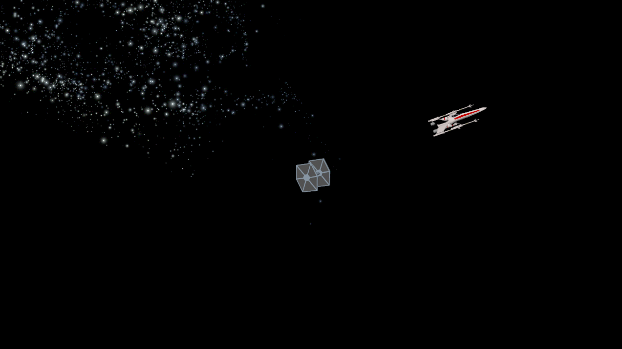
Final Animation
I feel that with more time I could of made even more as with any project but I feel that within the time I had my animation has come out the way I wanted it to and I even better than what I expected when I had put it all together. I feel if I had more time I could of added in music and sounds giving it more of an impact as I sat and watched it when showing it to my family and they said play it whilst playing the star wars music on YouTube so I did and to my surprise it was even better in my eyes.
Animation Scene 6


Animation Scene 5


Animation Scene 4


Animation Scene 3


Animation Scene 2

Animation Scene 1


Tie Fighter Texturing


X-Wing Texturing


Animation Attempt 1

Sunday, 11 December 2016
Relationship Exercise
In this exercise I had to pair up two objects so that when I moved the driver object the driven would also animate. I did this by first creating a cube and a sphere. I then selected the cube and selected key/ set driven key which brings up a menu where I then select who is the driver and who is the driven I select the sphere and click load driver and then I select the cube and click load driven. I then select what variables I want to alter I select translate X on the sphere and rotate Y on the cube after doing so I set a key for the sphere and then I move it along the X axis and then set a key again. I then set a key for the cube and added a rotation around the Y axis of 1800 after doing so I set another key so when I move the sphere I can see that the cube is also rotating. From this exercise I have learnt that these tools can be useful when creating for example a train where all the pieces move together in one smooth motion.


Hand Rigging Exercise
In this exercise I had to take a object of a had and rig it so it could move at individual points. I did this by first going to the rigging tab and selecting the joint tool. I then added in the different joints to the hand for each individual finger. I then moved the joints into player and selected both the joints and the mesh. I then went into rigging mode and went to skin/ interactive bind ski, which applied the joints to the mesh, and allowed me to change how much of an area each joint would effect when manipulated. I then manipulated the joints with the move and rotate tool. I can see that this is a vital tool when creating characters or less rigid models such as people. I also found this very easy to accomplish with no problems.


Bouncing Ball Exercise
In this exercise I had to create a animation of a ball bouncing from this diagram.
 To start creating this animation I first created a sphere. I then used the Bezier curve tool to create the curved motion path the ball moves along. after doing this I attached the ball to the motion path by going into animation mode and going to constrain/ motion path which automatically attached the sphere to the motion path and animated it. I then went in to each fram manipulating the sphere so it would get the different shape as if it was bouncing.


 I found this task fairly easy to accomplish without any problems. I can see that maya is very useful in automatically creating animations along motion paths and that this will benefit me a lot in creating my animation. I have also seen that by editing the animation frame by frame by using key frames that it can become a long procedure to do depending on the quality and length of the animation.
Skybox Exercise
In this Exercise I had to create a sky box in Maya. I did this by first creating a sphere and deleting the bottom half of faces. I then proceeded to add a few more divisions to the object. I then used the mesh display, reverse tool to set the normals of the object from the outside to the inside of the object so the textures would display on the inside. I then create a new material and added the surface shader material type to it so that it wouldn't interact with any light sources or cause any shadows. I then went and added the sky box file to the material creating the sky. I find this to be very useful and easy to do as your able to create the entire area your animation will be set in very quickly, and after using these tools I will be able to create my sky box in my star wars animation allowing there to be an enviroment that the animation plays in.


Friday, 11 November 2016

Star Destroyer part 5

In this part I started by creating to cubes and lining the centre points of those cubes up with the schematics. After doing so I pulled the bottom edge of the first cube backwards. I then added two more edges to the second cube and moving all of the edges of that cube to form the diamond shape of the command deck. I then moved onto creating the sensors on the top I did this by creating 2 spheres and changing the number of faces they had to get that rough texture to them. I then made several cubes and moved them to create the joists that connect the sensors to the command deck. I found this easy although I struggled to find how to lower the number of faces on the spheres at first.
Star Destroyer Part 4

Star Destroyer Part 3

After creating the main body I proceeded to create the life support on the bottom of the star destroyer. I did this by first creating a sphere and positioning it with the move tool so it was in line with the schematics. I then used the scale tool to get the right size. after getting the sphere to the right size I went inside the object and selected all the faces that wouldn't be visible to the viewer and deleted them to make it more efficient. I found this easy to do as it was using the tools I feel I have become very familiar with such as the scale tool.
Thursday, 10 November 2016
Star Destroyer Part 2


Tie Fighter Part 3
Tie Fighter Part 2
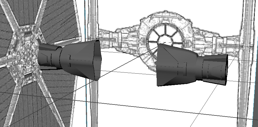
The first step to creating my Tie fighter was the body. I began by creating a sphere and lining it up with the schematics. I then proceeded to use the multi-cut tool to create a circular edge on the inner faces of the sphere I then cut straight lines following the schematics for the windows of the cockpit. I then used the extrude tool to push them backwards into the sphere. After creating the windows I went on to creating the small details on the top and bottom by using the multi-cut tool to cut a curve across the top and bottom and then using the extrude tool to pull them out of the sphere. After so I created two cubes lined them up with the top of the cockpit and then selected the cockpit and one cube and then used the Boolean tool to cut the cubes out of the sphere to create the indents on the top. I then extruded the inside faces on the back of the sphere 2 the first one was forwards to create the engine shape and the second back to create the inside of the engine.


X-Wing Part 5

X-Wing Part 4

X-Wing Part 3

UV Mapping Exercise
In this exercise I had to apply a cardboard box texture to a cube and then using the UV map editor I had to align the texture with the cube to get the right appearance.
First I created a cube and then applied a Lambert material to it. after doing so I used the UV map editor to move the UV Vertices to align them with the texture. I found this very easy to do although I can see this becoming more complicated when working with round or more complex shapes.


First I created a cube and then applied a Lambert material to it. after doing so I used the UV map editor to move the UV Vertices to align them with the texture. I found this very easy to do although I can see this becoming more complicated when working with round or more complex shapes.
Subscribe to:
Comments (Atom)