Friday 11 November 2016

Star Destroyer Part 6

This is the finished Star Destroyer.

Star Destroyer part 5

In this part I started by creating to cubes and lining the centre points of those cubes up with the schematics. After doing so I pulled the bottom edge of the first cube backwards. I then added two more edges to the second cube and moving all of the edges of that cube to form the diamond shape of the command deck. I then moved onto creating the sensors on the top I did this by creating 2 spheres and changing the number of faces they had to get that rough texture to them. I then made several cubes and moved them to create the joists that connect the sensors to the command deck. I found this easy although I struggled to find how to lower the number of faces on the spheres at first.

Star Destroyer Part 4

I then began making the engines of the star destroyer I did this by first creating a cylinder and using the scale tool to get it to the right size. I then used the multi-cut tool to create vertexes on the front faces I then extruded these backwards. I then selected the edges around the object and used the bevel tool to bevel them. I then proceeded to duplicate it multiple times and position and scale them to the appropriate sizes. I then made 2 cubes to connect the main 3 engines. I found this easy to do and have found that these tool allow me to manipulate objects easily.

Star Destroyer Part 3

After creating the main body I proceeded to create the life support on the bottom of the star destroyer. I did this by first creating a sphere and positioning it with the move tool so it was in line with the schematics. I then used the scale tool to get the right size. after getting the sphere to the right size I went inside the object and selected all the faces that wouldn't be visible to the viewer and deleted them to make it more efficient. I found this easy to do as it was using the tools I feel I have become very familiar with such as the scale tool.

Thursday 10 November 2016

Star Destroyer Part 2

After setting up my schematics I began creating the main body of the star destroyer. I began with making a cube and moving the vertexes to the corners of the star destroyer schematics I then used the point weld tool to join the vertexes at the front up. After doing so I extruded the top and bottom and used the multi-cut tool to create a edge going through the middle of the model. I then pulled the back vertex for that edge up to create the triangular shape of the star destroyer. I then proceeded to go to the top view and use the schematics and the multi-cut tool to draw out the different levels of the star destroyer and then select those faces and extrude them to different heights. I then made another cube and placed it underneath and used the Boolean tool to cut the cube out of the star destroyer to make the bay underneath it. I found this easy to accomplish as I feel I have developed my skills with the multi-cut tool over the period I have been working on these models.

Tie Fighter Part 4

This is the finished Tie Fighter

Tie Fighter Part 3

After creating the wings and body I began creating the connectors that connect the wings to the body. I did this by first creating two pipes and using the scale tool to get them to the same size as the schematics. after doing so I selected the top 4 and bottom 4 of the pipe and used the scale tool to pull them out. I then did this again on the right side. I then used the multi-cut tool to draw out the different details on the connectors I then extruded all of these details and then duplicated the connector.

Tie Fighter Part 2

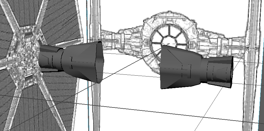
The first step to creating my Tie fighter was the body. I began by creating a sphere and lining it up with the schematics. I then proceeded to use the multi-cut tool to create a circular edge on the inner faces of the sphere I then cut straight lines following the schematics for the windows of the cockpit. I then used the extrude tool to push them backwards into the sphere. After creating the windows I went on to creating the small details on the top and bottom by using the multi-cut tool to cut a curve across the top and bottom and then using the extrude tool to pull them out of the sphere. After so I created two cubes lined them up with the top of the cockpit and then selected the cockpit and one cube and then used the Boolean tool to cut the cubes out of the sphere to create the indents on the top. I then extruded the inside faces on the back of the sphere 2 the first one was forwards to create the engine shape and the second back to create the inside of the engine.

X-Wing Part 6

This is the finished X-Wing Model

X-Wing Part 5

After creating the wings I moved onto the weapons. To create the weapons I first created a 6 cylinders and lined them all up after doing so I used the multi-cut tool and held ctrl which makes the multi-cut tool be able to apply vertexes all the way around a cylinder. I did this 4 times on one cylinder and extruded them outwards. I then used the scale tool to get the cylinders to the right size so they lined up with my schematics. after doing so I then created a pipe rotated it by 90 so that it was sideways I then selected the left side of faces and deleted them I then used the point weld tool to join up the leftover vertexes. I then grouped all of them with ctrl+g and then duplicated the whole group 3 more times moving them into their positions. I found this easy to accomplish with little to no problems.

X-Wing Part 4

After creating the body I moved onto the wings. When creating the wings I first created a cube and then used the extrude tool and multi-cut tool to add edges to my shape I then positioned those edges and vertex in align with the schematics to get the right shape. I found this easy to accomplish as I have found that these tools have a variety of uses.

X-Wing Part 3

After creating the engines. I went on to making the main body of the X-Wing by first creating a cube and then using the extrude, scale and multi-cut tool to extend the body and to line it up with the schematics. after doing so I extruded the front faces to begin creating the nose of the X-Wing. I did this by move the top edges down with each increment. after finishing the nose I used the smooth tool to make it look more rounded. I found making the dose very difficult as at first I struggled to get the faces to extrude the way I wanted them to I fixed this by adding more faces and using the target weld tool to join vertexes.

UV Mapping Exercise

In this exercise I had to apply a cardboard box texture to a cube and then using the UV map editor I had to align the texture with the cube to get the right appearance.

First I created a cube and then applied a Lambert material to it. after doing so I used the UV map editor to move the UV Vertices to align them with the texture. I found this very easy to do although I can see this becoming more complicated when working with round or more complex shapes.


Bitmap Exercise

In this exercise I had to create a cube and apply a bitmap texture to it.
I did this by creating a cube from the create menu and then holding right click and selecting add material. Once I had done this the material selector to select Lambert which is a basic material that applies a mat material. after selecting the material I added a file to it which was the checkerboard texture and then after pressing 6 to display textures it appeared. 

Monday 7 November 2016

X-Wing Part 2

Once I had created the schematics in Maya and lined them all up I began by creating the engines. I created a cylinder and light it up with the schematics I then extruded the cylinder and scaled it down to create a smaller face. I created another smaller cylinder and used the multi-cut tool to create new edges to cylinder. I extruded these new edges I had created to add the detail to the engines. I found this easy to accomplish using the tool available to me.

Tuesday 1 November 2016

MoodBoard

These are the moodboards I have comprised to show the inspiration for my models